
General purpose motors have been around for many years. They are the workhorse of almost every industry.
An inverter-duty motor is a much newer concept that became necessary as motors began to be driven by VFDs (inverters or AC drives). An inverter duty motor can withstand the higher voltage spikes prodcuced by all VFDs (amplified at longer cable lengths) and can run at very slow speeds without overheating. This performance comes at a cost: inverter-duty motors can be much more expernsive than general purpose motors. Guidelines for choosing an Ironhorse general purpose motor vs an inverter-duty motor are given below. If your application falls within the guidelines below, there is no need to apply an inverter-duty motor.
Background: AC motors can be driven by across-the-line contactors and starters. The electricity sent to the motor is a very clean (ture) sine wave at 60 Hz. Noise and voltage peaks are relatively small. However, there are drawbacks: the motors can only run electrically at one speed (speed reduction is usually handled by gearboxes or some other, usually inefficient, mechanical means) and the inrush of electrical current (when the motor is first turned on) is usually 5 to 6 times the normal current that the motor consumes. The speed reduction apparatus is expensive and bulky,and the inrush can wreak havoc with power systems and loading (imagine an air conditioning system in an old house - when the compressor kicks on, the lights dim; now imagine the same circumstances with a motor the size of a small car).
Note: The following discussion applies only to 3-phase motors.
Enter the VFDs (Variable frequency drives):
Drives were introduced to allow the speed of these motors to be changed while running and to lessen the inrush current when the motor first starts up. To do this, the drive taks the incoming 60Hz AC power and rectifies it to a DC voltage. Every drive has a DC bus that is around 1.414 (sqrt of 2)* incoming AC Line Voltage.
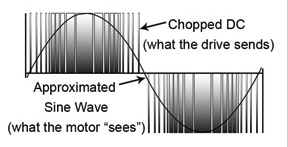
This DC voltage is then "chopped" by power transistors at very high frequencies to simulate a sine wave that is sent to the motor.B converting the incoming power to DC and then reconverting it to AC, the drive can vary its output voltage and output frequency, thus varing the speed of a motor. We get to control the frequency and voltage going out to the motor, thus controlling its speed.
Some things to watch out for:
A VFD-drvien general purpose motor can overheat if it is run too slowly. (Motors can get hot if they're run slower than their rated speed.) Since most genral purpose motors cool themselves with shaft-mounted fans, slow speeds mean less cooling. If the motor overheats, bearing and insulation life will be reduced. Therefore there are minimum speed requirements for all motors.
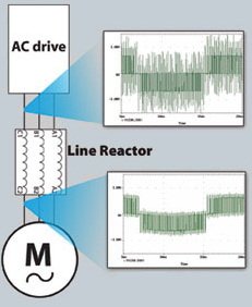
The voltage "chopping" that occurs in the drive actually sends high-voltage spikes (at the DC bus level) down the wire to the motor. If the system contains long cabling, there are actually instances where a reflected wave occurs at the motor. The reflected wave can effecitively double the voltage on the wire. This can lead to premature failure of the motor isulation. Long cable lengths between the motor and drive increase the harmful effects of the reflected wave, as do high chopping frequencies (listed in drive manuals as carrier frequencies). Line reactors,1:1 transormers placed at the output of the drive, can help reduce the voltage spikes going from the drive to the motor. Line reactors are used in many instances when the motor is located far from the drive.
In summary, gerneral purpose motors can be run with drives in many applications; however inverter-duty motors are designed to handle much lower speeds without overheating and they are capable of withstanding higher voltage spikes without their insulation failing. With the increased performance comes an increase in cost. This additional cost can be worth it if you need greater performance.


